WHERE IN THE IDE
Create with AI / Ask AI for BASIC; Tools → UDG Editor or SCREEN$ Graphic Editor for assets
Before you start
- Choose whether you need a loading SCREEN$, an 8×8 UDG or drawing code.
- Use your own artwork or material you have permission to use.
- For this exercise choose a 48K project and UDG slot A.
The current code assistant does not automatically see every graphic or native layer. Describe the dimensions, colour constraints and bytes it needs. Native graphic editing is a separate step.
STEP 01
Define a tiny asset with an observable shape
Start with an 8×8 arrow rather than a full animated scene. Ask for row bytes and the reasoning behind them. The output below is a request to the assistant, not a screenshot or a promise of pixel-perfect generation.
Design a right-pointing arrow as one ZX Spectrum 48K UDG in slot A.
Return eight rows of 0/1 pixels and their decimal byte values, with the most significant bit on the left. Explain how to verify each row.
If proposing BASIC, use authentic numbered Sinclair BASIC and the UDG base rather than an invented fixed address. Do not overwrite other UDG slots. No external files or colour-per-pixel claims.
STEP 02
Verify the bytes in the UDG Editor
Open Tools → UDG Editor and select slot A. Draw the suggested rows or enter the corresponding supported values. Compare the 8×8 preview with the binary rows: a reversed arrow usually means bit order was misunderstood. Use the editor’s generated BASIC as the concrete integration reference.
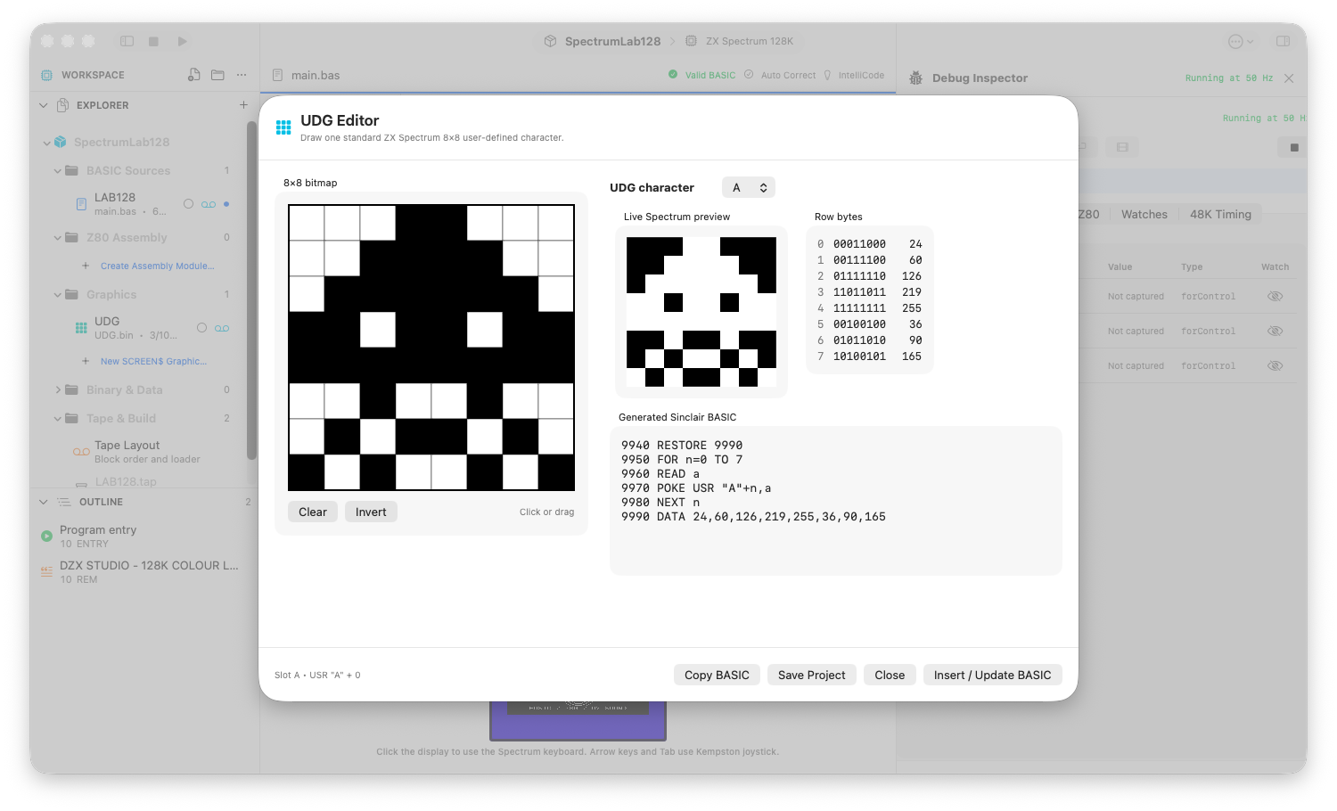
An 8 × 8 UDG, its row bytes, Spectrum preview and generated Sinclair BASIC.
STEP 03
Add a small display change
With a valid main BASIC program, ask contextual AI to show the UDG at a specified character cell. Include the actual generated UDG initialization and the current line-number constraints. Review both initialization and display order; displaying the glyph before initialization will not show the intended asset.
STEP 04
For a loading screen, work in the real canvas
Import a PNG/JPEG into SCREEN$ Graphic Editor, select Fit or Crop to Fill, and inspect the 256×192 bitmap and 8×8 attribute cells. Add editable text, reposition it and choose ink/paper before rasterizing. An attractive source picture can still convert poorly because of attribute clash.
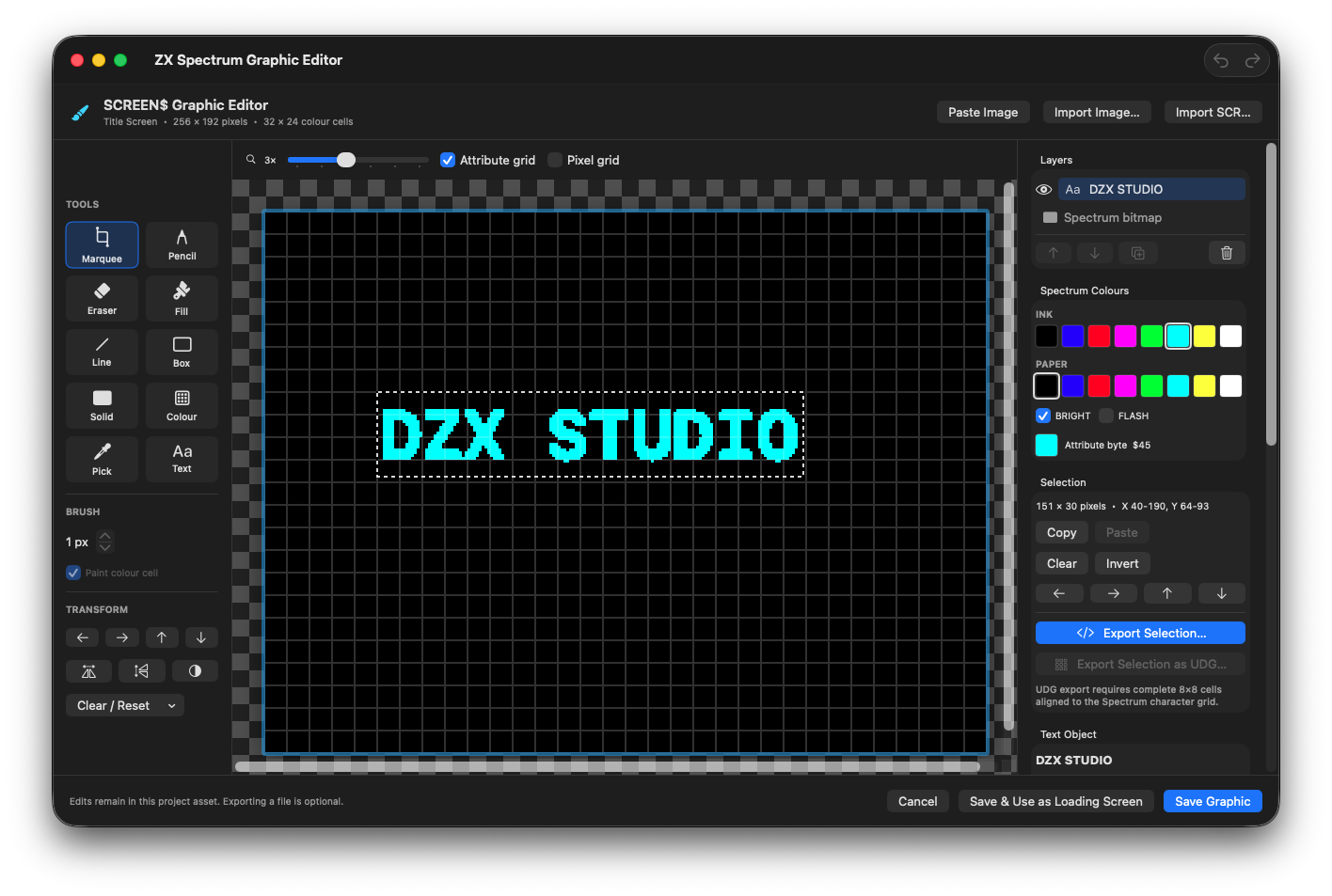
A bright-cyan DZX STUDIO text layer at X 40, Y 64. Its selection, colour palette and 8 × 8 attribute grid remain available before rasterizing.
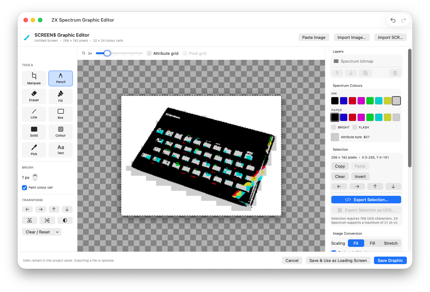
The original ZX Spectrum photograph converted to a 256 × 192 SCREEN$ in the Graphic Editor.
Photograph: Bill Bertram · CC BY-SA 2.5 · Converted to SCREEN$.
STEP 05
Ask for a constraint-aware revision
Describe the actual defect, such as a title crossing colour cells or an unreadable icon. Ask for a layout or code revision, then make and inspect the native asset change yourself. Do not assume the model can directly modify the open text layer through the current code assistant.
Advise only. My 256×192 loading screen has a title at the top and a 48×48 logo below. Title colours clash where letters cross 8×8 attribute cells. Suggest a layout with cell-aligned regions, one ink/paper pair per cell, and space for a two-line instruction. State coordinates and tradeoffs. Do not claim you have seen or edited my image.STEP 06
Include the asset in the build explicitly
Save the graphic and choose Use as Loading Screen when appropriate. Check that Tape Layout and the loader agree on the SCREEN$ block. Build and run a fresh TAP; an editor preview alone does not prove that the distributed program loads the asset.
If something goes wrong
- The model promises independent colours for every pixel
- Restate the 8×8 attribute-cell restriction and redesign the image around ink/paper regions.
- The generated icon is mirrored
- Compare the row bits to the native preview. Verify bit order before changing display code.
- The asset looks correct but never appears at runtime
- Check initialization or tape inclusion, loader order and the current build; do not regenerate the artwork first.
READY TO MOVE ON?
Check the result, not just the response.
- The UDG shape or converted screen is readable at real Spectrum resolution.
- Attribute limitations are intentional.
- The fresh TAP loads the asset in the expected order.